
This article is designed to review all the basics around spine anatomy that would be helpful for performing procedures. Any pain management inverventionalist/proceduralist will rely on this basic anatomy, understanding of fluoroscopy images and C-arm use. It is written with a few basic goals:
- Review basic vertebrae and spine anatomy
- Discuss that in the context of fluoroscopic images and C-Arm positioning for procedures
- Outline basic principles that can set a foundation for the various articles on this site
Cervical imaging can be tricky. Spending time upfront on getting good imaging can make the procedure much smoother.
Table of Contents
Overview
We’ll reference these planes.

Position the patient carefully
- Try to position the patient so the neck is in a “long”, neutral position.
- A twisted neck can make lateral and AP views misaligned.
- Avoid flexion, except CESIs where you want the head flexed on the neck.
- Hunched shoulders can obscure the lower levels of the neck in a lateral view.
- Try to have the shoulders pulled down slightly and/or curled forward to get them out of the way.
Take into account body habitus
- Obese patients often have fat that limits access to the injection site or obscures the image.
- If the patient is in a prone position you can tape back pannus: apply tape near the base of the neck and pull down a long strip towards the low back (ie following the spine).
- This pulls down some of the pannus out of the way.
- Hair can get in the way
- Have patients wear a bouffant with hair tied inside. All of this can be taped up after positioning.
Lateral View
- Most work (medial branch blocks, epidurals, radiofrequency ablations) is done in the lateral or oblique view (as opposed to an AP view, which is more important for lumbar/thoracic work)
- Line up the borders of the lateral mass/articulating column so you don’t see “double images” when the left and right are out of alignment.

C-Arm Positioning
After obtaining a good lateral view simply rotate the c-arm in one axis to get the AP view. This minimizes motion of the c-arm so it’s easy to re-establish your lateral view if needed.
Troubleshooting Images
Below is an example from the cervical medial branch block guide outlining our targets.
- If this were the fluoro image it would generally be workable, but it isn’t perfect.
- Can you see where it’s off?
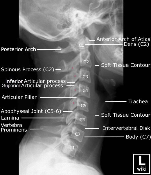
C3 and C4 are the most obvious examples of slight misalignment. Compare to a version with outlines along the posterior borders of the lateral masses.
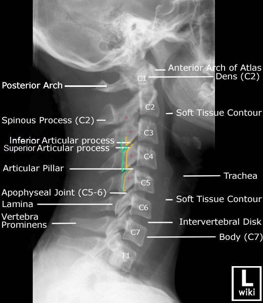
- You can see the green and yellow lines are mostly misaligned vertically
- The vertical lines are the posterior border of the lateral masses.
- This means that your x-ray beam isn’t in a perfect frontal plane.
- A slight tilt in that plane alone will fix this misalignment.
When setting up the procedure, the initial imaging can look very messy. It’s often helpful to align one plane at a time as in the example above.